Hardware Setup›Assembly
ABC Hardware Setup
Table of contents
#Shopping list
#Bill of materials
For The main mount
| Item | Qty | Link |
|---|---|---|
| Robot mounting 3060 extrusion (base rail, A) | 1 | Amazon |
| 200 mm extrusion for mounting the camera back (B) | 1 | Amazon |
| 1 m black extrusion for camera (F) | 1 | Amazon |
| Corner connector pack for 3030 extrusions: 24 black 2835 brackets C, 48 M6 T-nuts D and 48 bolts E — used for the A–B and B–F joints here and for the cage struts | 1 pack | Amazon |
| M6 bolts (assortment) — the 10 mm one for the top camera mount comes from here | 1 pack | Amazon |
| M6 T-slot sliding nut (D) for the top camera mount, in addition to the ones in the bracket pack (pack of 20 — the same pack covers the 8 nuts for mounting the robot) | 1 | Amazon |
| Intel RealSense D405 (top camera) | 1 | Amazon |
| Top camera mount (3D printed, see 3D printed parts) | 1 |
For Mounting the robot
| Item | Qty | Link |
|---|---|---|
| YAM arm | 2 | I2RT |
| M6 T-slot sliding nuts (D), 4 per arm (from the same pack of 20 as in the main mount) | 8 | Amazon |
| M6 × 20 mm bolts, 4 per arm (from the M6 assortment above) | 8 | |
| Robot table — adjustable height, with lockable wheels | 1 | |
| Irwin Quick-Grip mini clamps, one at each end of rail A (sold in packs of 2 — 4 clamps are needed in total, 2 here and 2 for the workspace, so order 2 packs) | 2 | Amazon |
For Mounting the wrist camera and gripper
| Item | Qty | Link |
|---|---|---|
| Crank gripper (optional but recommended). The wrist camera mount comes with it. | 2 | I2RT |
| Intel RealSense D405 (wrist cameras) | 2 | Amazon |
For Cage building
| Item | Qty | Link |
|---|---|---|
| 3030 extrusions, 1220 mm (48 in), for the cage: 2 used uncut, 4 cut to 39 in, 4 cut to 35 in (sold in packs of 4 — order 3 packs, 2 spare) | 10 | Amazon |
| 3-way corner cubes for 8020 extrusions | 1 pack | Amazon |
| Black 2835 corner brackets (C) with M6 T-nuts and bolts, for the last two vertical struts (2 per strut) — from the same 24-piece pack as in the main mount | 4 | Amazon |
| White project board, one per covered side (back and two sides) | 3 | Office Depot |
| Double-sided adhesive tape, to stick the boards to the frame | 1 | Amazon |
For Wiring and electronics
| Item | Qty | Link |
|---|---|---|
| JSER USB camera cables, one per D405 | 3 | Amazon |
| USB cable, one per arm (the arm has a built-in USB-CAN interface) | 2 | Amazon |
| Zip ties | 1 | Amazon |
For The robot workspace
| Item | Qty | Link |
|---|---|---|
| Workspace table, at least 48 in × 39 in (1220 × 990 mm), the cage footprint | 1 | |
| Irwin Quick-Grip mini clamps, to clamp the cage to the robot table (same pack of 2 as for mounting the robot — 4 clamps total, order 2 packs) | 2 | Amazon |
#3D printed parts
| Item | Qty | CAD |
|---|---|---|
| Top camera mount — holds the top D405 on post F (The main mount, step 3) | 1 | Download STL |
| Wrist camera mount — D405 bracket on each gripper (Wrist camera and gripper, step 2) | 2 | ships with the arm |
| Gripper fingertips — one pair per gripper | 4 | ships with the arm |
#Tools
- Allen keys
- Electric screwdriver, for the gripper and camera-mount screws
- X-acto knife or similar, to cut out the board
#Assembly
#The main mount
In this section, we will build the primary mount for the robot and the top camera. The mount should approximately replicate the simulation environment: the empty bimanual scene abc_sim/models/yam_bimanual_empty.xml, which abc_sim/scene_xml.py loads and transforms at run time. The lower half of Figure 1 is a render of that scene with the dimensions we are matching.
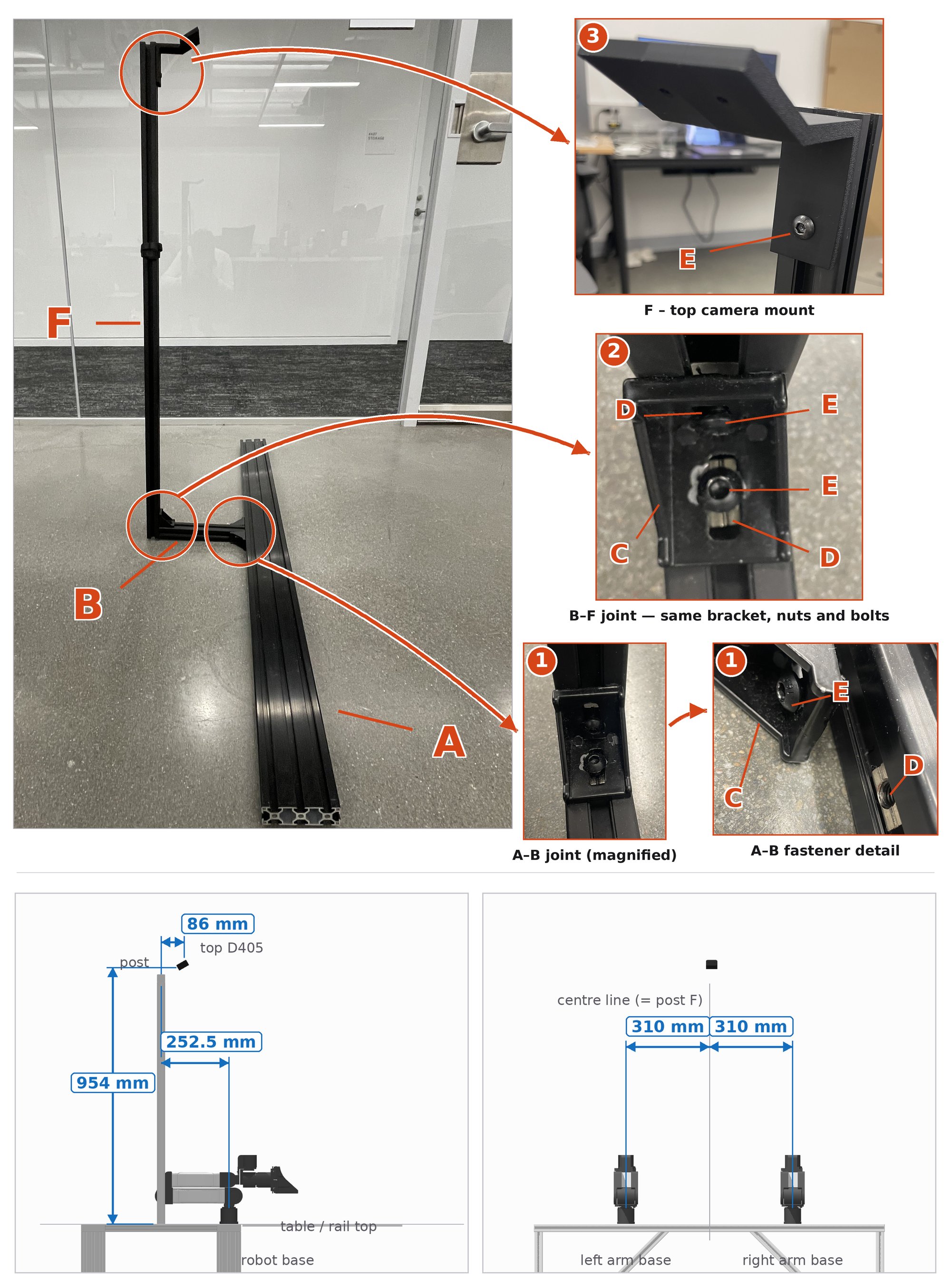
yam_bimanual_empty.xml rendered with MuJoCo — the top D405 sits 954 mm above the rail top and 86 mm forward of the post; the robot bases are 252.5 mm from the post plane and 310 mm either side of the centre line. The sim's gate arch is hidden in the front view; on the real mount its place is taken by the single centre post F.- Start with the 3060 Robot Mounting Extrusion (A) and attach the 200 mm extrusion (B) to it at the midpoint, using the black 2835 corner brackets (C), M6 T-slot sliding nuts (D) and M6 bolts (E).
- Now attach the 1 m extrusion (F) to B using the same joint as in 1.
- Now attach the top camera mount to F using a 10 mm M6 bolt (E) and another sliding T-nut (D). The camera mount is 3D-printed (see 3D printed parts).
#Mounting the robot
Now, we will mount the robot on the mount we built in The main mount.
Robot base
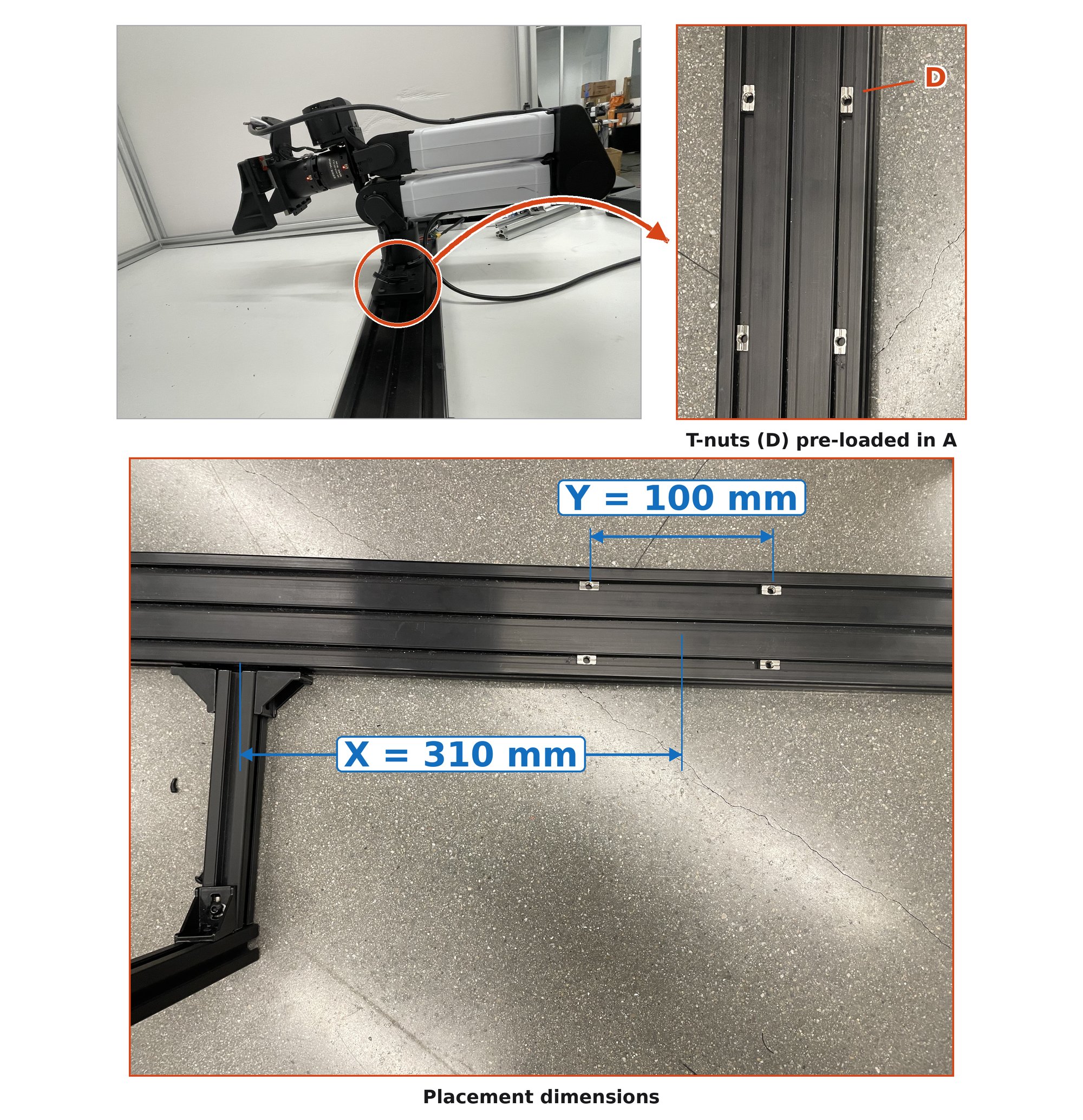
yam_bimanual_empty.xml) and Y = 100 mm (the YAM base plate is 200 × 70 mm with Ø6 mm mounting holes at ±50 and ±90 mm along it and ±20 mm across; the four nuts use the ±50 mm pair, 40 mm apart across the rail).- Slide in 4 sliding T-nuts into the base rail we set up in The main mount. Then, screw in the robot base to it using M6 20 mm bolts.
- Do this symmetrically for the robot on the other side with the same dimensions.
Clamping to the table
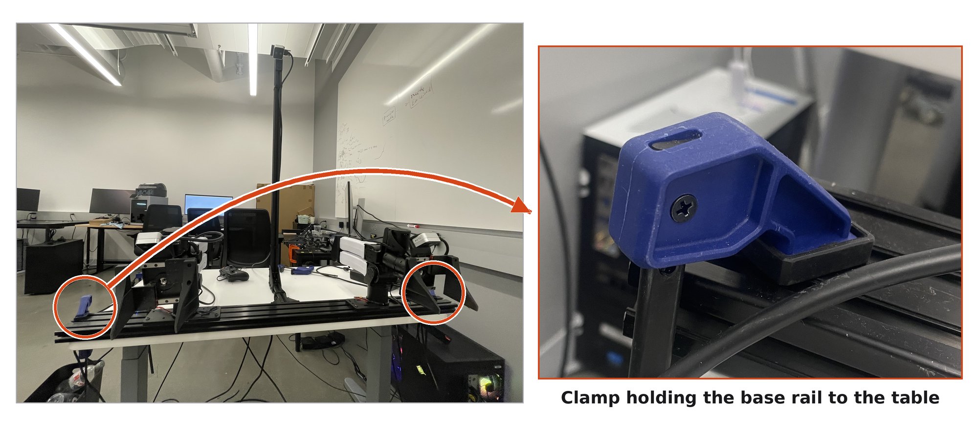
- Clamp the setup above to the top of a table (preferably adjustable height and with lockable wheels). See Figure 3.
#Mounting the wrist camera and gripper
Now, we would like to add a gripper and wrist camera to our robot. Our dataset is primarily collected on crank shaft grippers, linear gear grippers and adaptive flexpoint grippers. A larger fraction of the data is with the crank shaft gripper, so for better performance we recommend using this. The camera mount comes along with the gripper from the vendor I2RT.
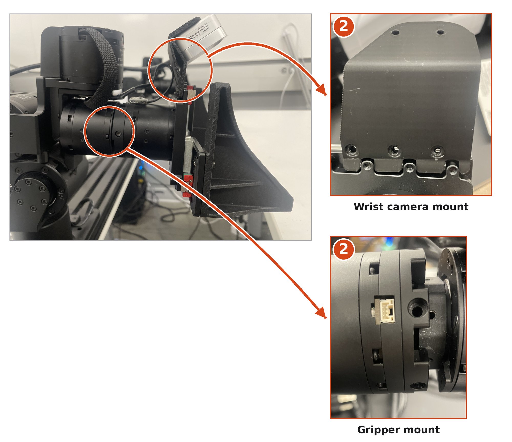
- Push the gripper onto the ends of the arms. Important: sometimes (for the crank shaft gripper with YAM / YAM-Pro), this fitting is quite tight and requires forceful pushing with the ends properly aligned.
- This step is just screwing parts together, should be fairly simple with an electronic screwdriver. Tightly screw in the gripper to the arm with the long screws that come with the robot. Then screw in the camera mount with the screws that come with it, and finally screw in the D405 with the holes on the mount.
- Repeat 1, 2 for the other arm.
#Cage building instructions
We will need 10 extrusions to build the cage:
- 2 of 48 in (uncut, as bought — 1220 mm)
- 4 cut to 39 in
- 4 cut to 35 in
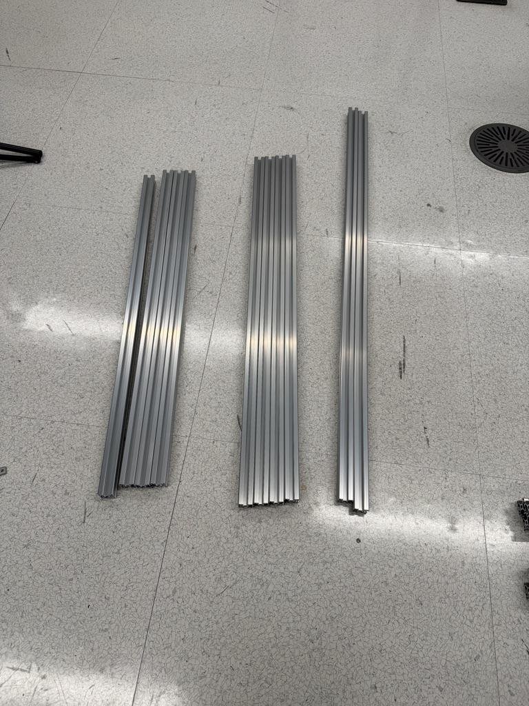
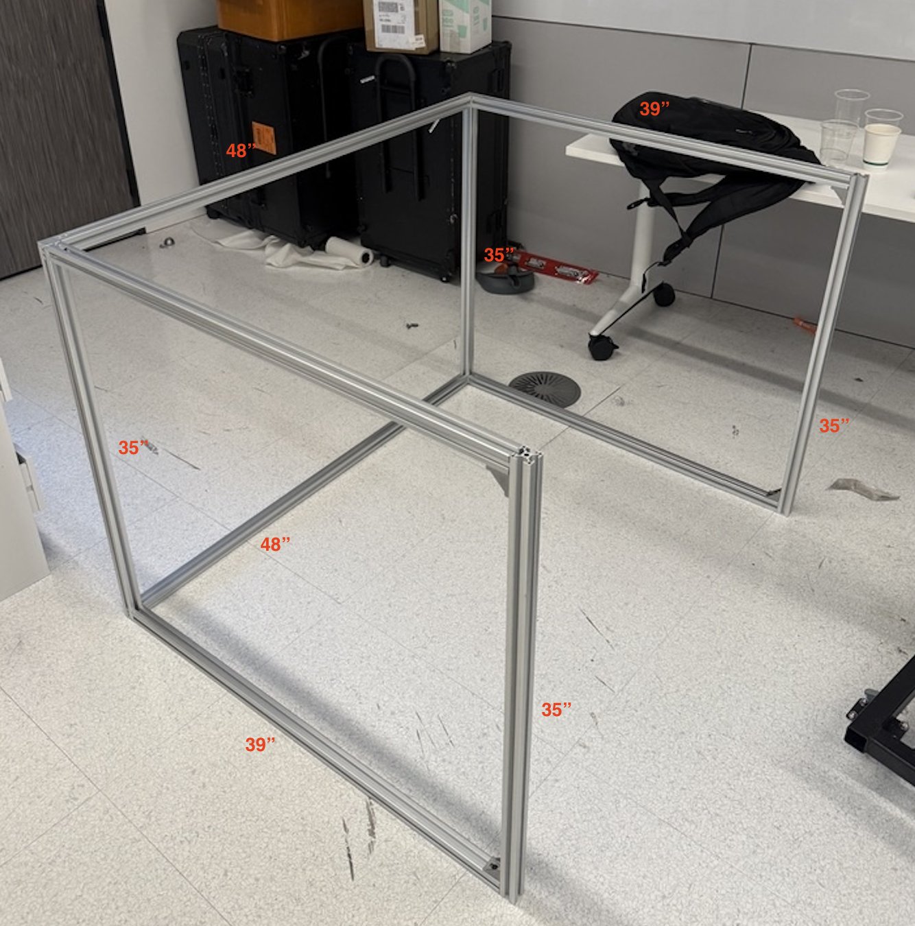
We will build the back of the cage first.
- Attach the four corners using the 3-way connectors. The 48″ extrusions form the cross beams and the 35″ form the vertical. Important: ensure that all the extra corner connectors are pointing out in the same direction.
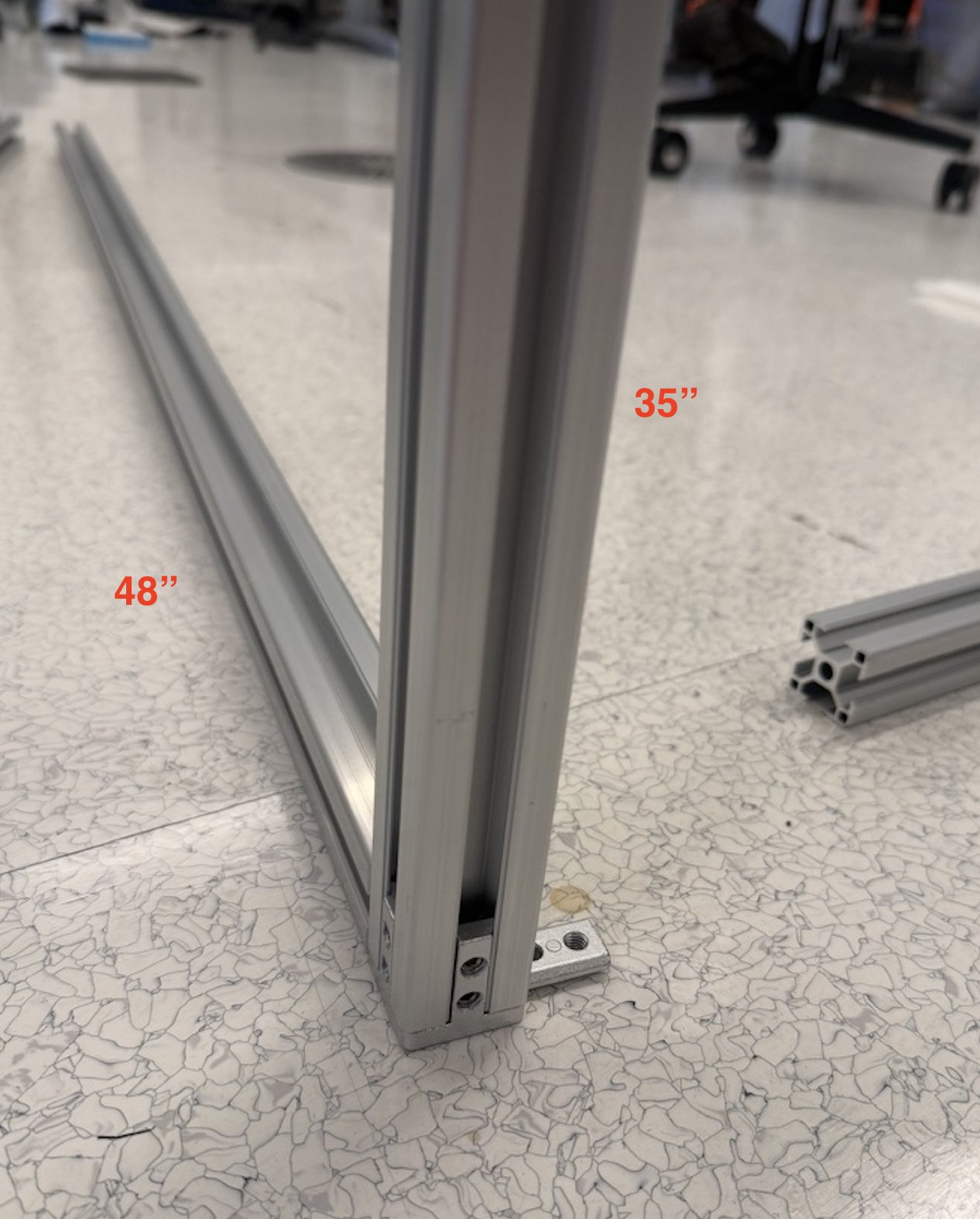
Start of the back frame. 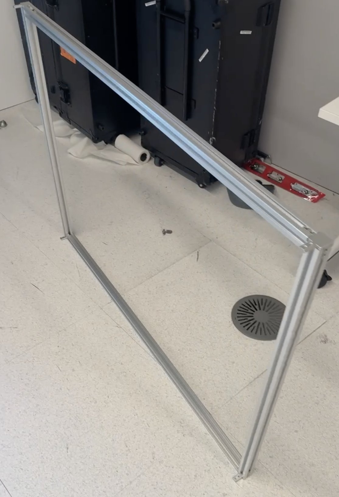
The result after the four corners. - Attach the bottom two connectors as follows.
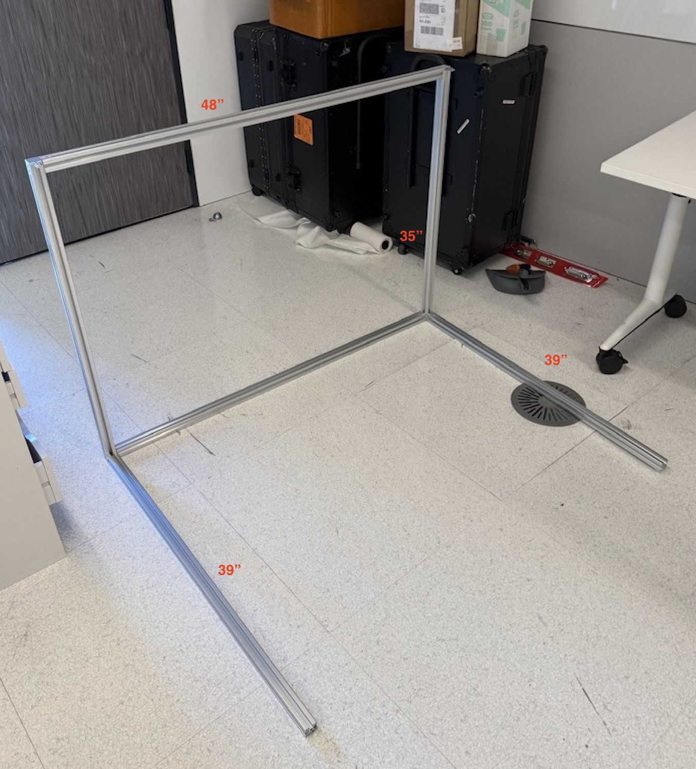
- Then attach the last two vertical 35″ struts using the black 2835 corner brackets (C), two per strut.
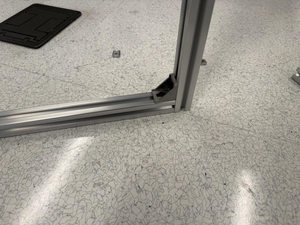
- We then bolt them together — with corner connectors — to make a frame that looks like this.
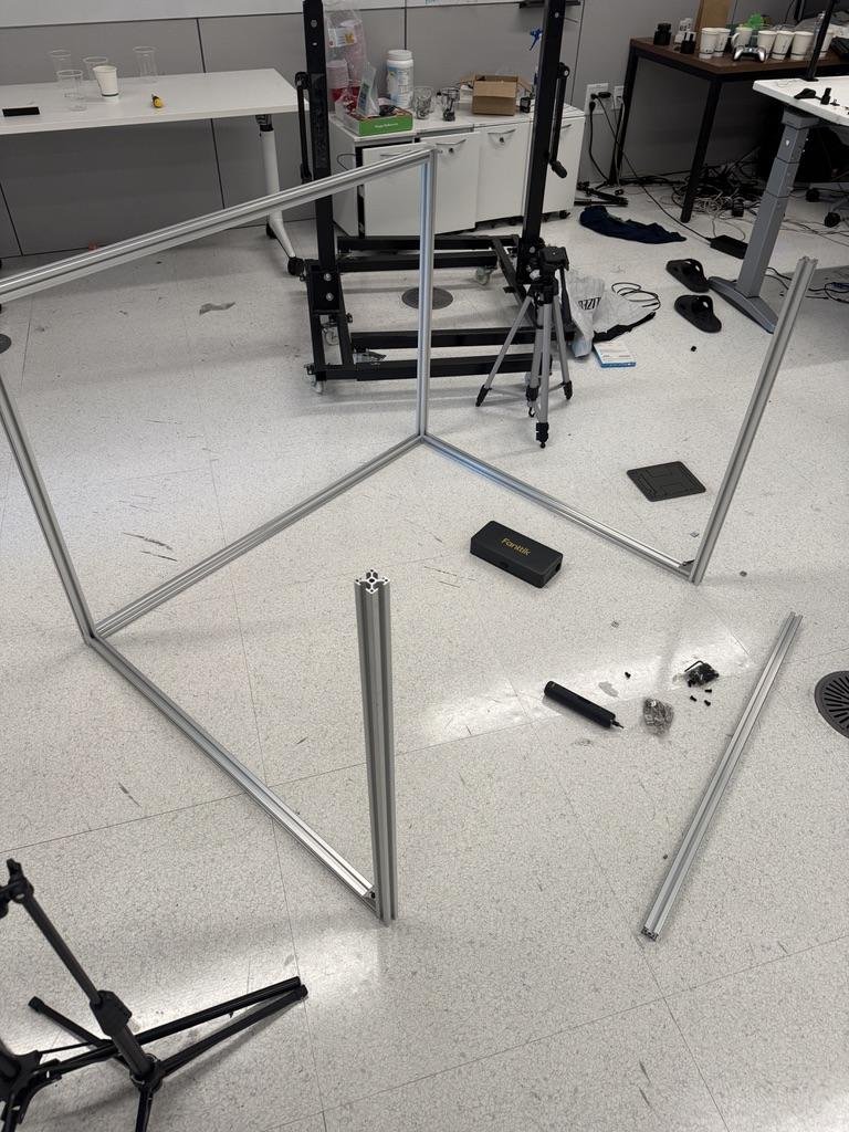
- Finally, use two more corner connectors and attach the remaining side of the back of the cage to complete it.
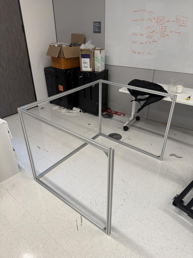
- You then want to cut out the project board to dimensions matching the size of the sides (so around 35 in × 41 in). Use double-sided tape to stick the boards to the cage boundary from all sides.
#Wiring and electronics
#Cameras
- Use JSER cables to connect the three cameras to the computer using USB ports.
- Prefer USB3 for avoiding intermittent packet drops. If your compute does not have USB3, disable the depth stream of the camera in the
deploy/folder in the code to reduce bandwidth requirements. - Use zip ties to secure the cable to the robot to the extent possible.
#Robot arms
- Connect each arm to the computer with a USB cable (a USB2 port is fine). No separate USB-CAN adapter is needed; the arm shows up as a CAN interface.
- Power each arm from its 24 V supply into the connector on the arm base.
- Check that both arms show up:
ip link show type can - Add your station to
PROFILESindeploy/robot/config.pywith the two CAN interface names or serials. - Run:
export ROBOT_PROFILE=<your_profile> sudo -E bash deploy/scripts/setup_can_names.sh - Verify:
Both should showip -details link show can_l_foll ip -details link show can_r_follstate UPandbitrate 1000000.
#The robot workspace
In this section, we set the robot workspace up. The dataset is collected on a rectangular workspace placed parallelly adjacent to the robot, with the cage as the visual background. While performance without the cage is not completely zero, it is much better with the cage on.
- Choose a table of about 48 in × 39 in (1220 × 990 mm), the footprint of the cage. Preferably, the dimension away from the robot should be greater than the cage dimension (39 in).
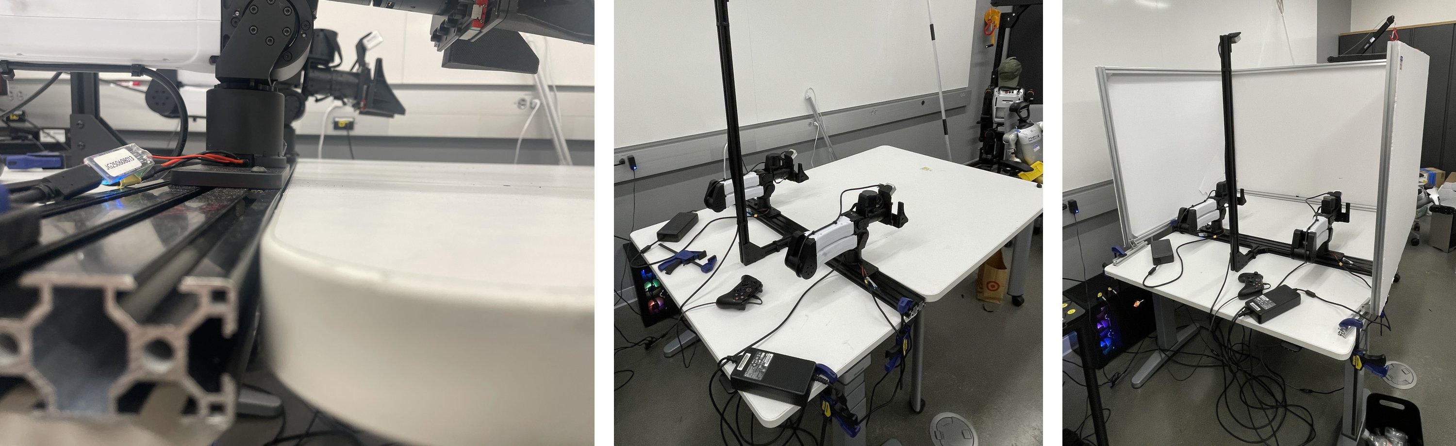
- Align the table with the base of the robot as in Figure 5 (left): the table top sits flush with the top of rail A, level with the bottom of the robot base plate.
- Put the cage on and clamp it to the other table on which the robot is mounted on. Your workstation would probably end up looking like as in Figure 5 (right).